

Magnet Guide
Core magnet facts, magnetic poles, field behavior, and common materials.
Magnet Terms
Magnetic field, poles, pull force, N-grade, and Gauss.
Neodymium Magnets
Common shapes and careful handling.
Bar Magnets
Pole orientation, field patterns, material options.

Using This Guide
Its guides move from core concepts to materials, shapes, and applications.
Magnet Basics
The basic picture has three parts: a magnet, a field around it, and forces that appear when the field meets another magnet or a responsive material. These ideas explain why two magnets can move together or push apart. They also distinguish pole-to-pole behavior from a magnet’s pull on iron. The magnet guide offers a fuller explanation of field patterns and related terminology.
What Is a Magnet?
A magnet is an object or material that produces a magnetic field, a region in which magnetic forces can act. The field extends beyond its surface, allowing a magnet to affect another magnet without direct contact; distance and orientation change the force observed. A magnet can also exert force on suitable magnetic materials such as iron, even when the material is not itself a magnet.
In many solids, microscopic magnetic moments contribute to the overall effect; when many moments share an alignment, their contributions combine into an external field. This is why a steel paper clip can move toward a nearby magnet, while a plastic clip does not respond in the same way. The word magnet names the source of the field, while magnetism describes the physical interaction that field produces.
Poles and Magnetic Fields
A magnet has two magnetic poles, called north and south, which describe regions associated with its field. On a bar magnet, these regions are near opposite ends, although their positions depend on the magnet’s shape. A compass placed nearby turns to align with the local field, giving a practical way to trace its direction.
In diagrams, magnetic field lines are drawn as closed curves. By convention, the part outside the magnet runs from north to south; the arrows show the direction a north test pole would be pushed, not paths made of material threads. Lines drawn closer together represent a stronger field in that region, so diagrams often show them crowded near a pole. The lines continue through the magnet from south to north, completing each curve. If a bar magnet is divided, each piece has both a north and a south pole rather than one isolated pole. This model explains how a field can influence objects across an air gap. Consult the magnet guide for a fuller explanation of field patterns, pole behavior, and magnet terminology.
Attraction and Repulsion
Two magnets interact according to the poles facing one another: a north pole and a south pole attract, while two north poles or two south poles repel. Turning one magnet end for end changes which poles face, so the direction of the force can be tested by changing its orientation. This rule describes interactions between magnets; it is not the whole explanation for a magnet’s pull on iron.
Iron is ferromagnetic, and a nearby magnetic field can align regions of its magnetic domains so the side closest to the magnet behaves like an induced opposite pole. This attraction can occur with either end of the magnet, so an iron object does not need a labeled north or south pole to be pulled in. When checking an unknown object against a known magnet, attraction alone cannot confirm that the object is a magnet. Repulsion from one pole is the more useful practical sign, because it demonstrates that like poles are facing.
Permanent and Temporary Magnets
Magnetic behavior depends on how readily a material’s internal regions respond to an applied field and how much alignment remains afterward. This distinction helps explain why a steel object can act magnetically in one setting but lose most of that effect when the field is removed. It also separates self-contained magnets from devices that need an electrical supply. The material and the source of the field determine which type is useful in a given application.
Permanent and Temporary Magnetism
Permanent and temporary magnetism differ in how strongly a material resists losing its magnetization. In permanent-magnet materials, magnetic domains can remain aligned after the external field is removed; in soft magnetic materials, alignment is easier to produce but also easier to undo.
| Material | Response while a field is applied | Behavior after removal |
|---|---|---|
| Soft iron | Its domains align readily, so it becomes strongly magnetized in an external field. | Because it has low coercivity, much of its magnetization disappears when the field is removed. |
| Electrical steel used in transformer cores | Its domains respond to the changing field generated by alternating current. | It is designed for repeated magnetization and demagnetization, though a small residual effect may remain. |
| Neodymium-iron-boron (Nd₂Fe₁₄B) | A strong field aligns domains during magnetization. | Its high resistance to demagnetization lets it retain useful magnetization without an applied field. |
| Barium ferrite (BaFe₁₂O₁₉) | Its domains align when the material is magnetized. | It retains magnetization after the external field is removed, making it a permanent-magnet material. |
The key property is coercivity: a material with low coercivity is readily magnetized and demagnetized, while one with high coercivity resists changes to its domain alignment. Temporary magnetism is therefore a material response, not a separate source of energy; the strength of the remaining magnetization depends on the material’s composition and magnetic history.
Permanent Magnets and Electromagnets
Permanent magnets produce a magnetic field without a continuous power supply because their material retains aligned magnetic domains. Alnico, ferrite, and neodymium-iron-boron are examples of materials used to make them. Their field remains present during ordinary use, so they suit applications such as a refrigerator door seal or a magnetic cabinet catch. Electromagnets produce a field when electric current flows through a coil; a soft-iron core inside the coil can strengthen its effect. Switching off the current removes most of the field, while changing the current or coil design changes the electromagnet’s output. The Permanent and Temporary Magnets guide explains how permanent-magnet behavior differs from temporary magnetization. Choose a permanent magnet for a field that needs no power, and an electromagnet when switching or controlling the field is essential.
Neodymium Magnets
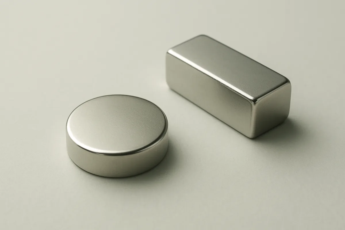
Neodymium magnets are a powerful family of permanent magnets made from a neodymium-iron-boron alloy. Their high magnetic performance allows a compact magnet to produce a strong field compared with many other materials. Material composition and protective coatings affect how these magnets perform and resist corrosion. Common shapes and careful handling are also important when choosing one for a particular use.
Neodymium Magnet Materials
Neodymium magnets, often called NdFeB magnets, are sintered permanent magnets based on the compound Nd₂Fe₁₄B. The formula describes the main crystalline phase; commercial alloys can include praseodymium alongside neodymium, with iron making up most of the material and boron typically around 1% by weight. Small additions of elements such as dysprosium or terbium may be used in some grades to improve resistance to heat-related demagnetization.
NdFeB magnets deliver strong magnetic performance for their size, which is why they are used in compact motors, speakers, sensors, and magnetic fasteners. Their high strength distinguishes them from ferrite magnets, which are generally larger for comparable magnetic tasks. Performance varies by grade and design, so the material name alone does not specify the force of a finished magnet.
Because the iron-rich alloy can corrode when exposed to moisture, most sintered neodymium magnets have a protective surface coating. A common finish is nickel-copper-nickel; zinc and epoxy coatings are also used for different environments and surface requirements. Coatings reduce corrosion but can be scratched or chipped, exposing the alloy. Choose a coating suited to the surroundings, and do not assume a coated magnet is waterproof.
Shapes and Handling
Neodymium magnets are made as discs, blocks, rings, and cylinders, as well as countersunk discs and curved segments for assemblies such as motors. A ring has a central opening for a shaft or fastener, while a block offers flat faces for mounting. Shape affects how a magnet fits and how its field is distributed, so dimensions and geometry matter alongside the material.
Sintered NdFeB is hard but brittle, not flexible like a soft metal. Dropping magnets or letting them collide can chip or crack them; fragments may have sharp edges. When two strong magnets attract, they can accelerate together and pinch fingers, especially when their faces meet across a small gap. Slide magnets apart rather than pulling directly when they are already joined.
Keep neodymium magnets away from magnetic-stripe cards, compasses, mechanical watches, and devices or storage media that can be affected by strong fields. The appropriate separation depends on magnet size and the device. For everyday use, choose a coated magnet in a shape that fits the job, and handle it slowly to reduce impacts and pinches.
Bar Magnets
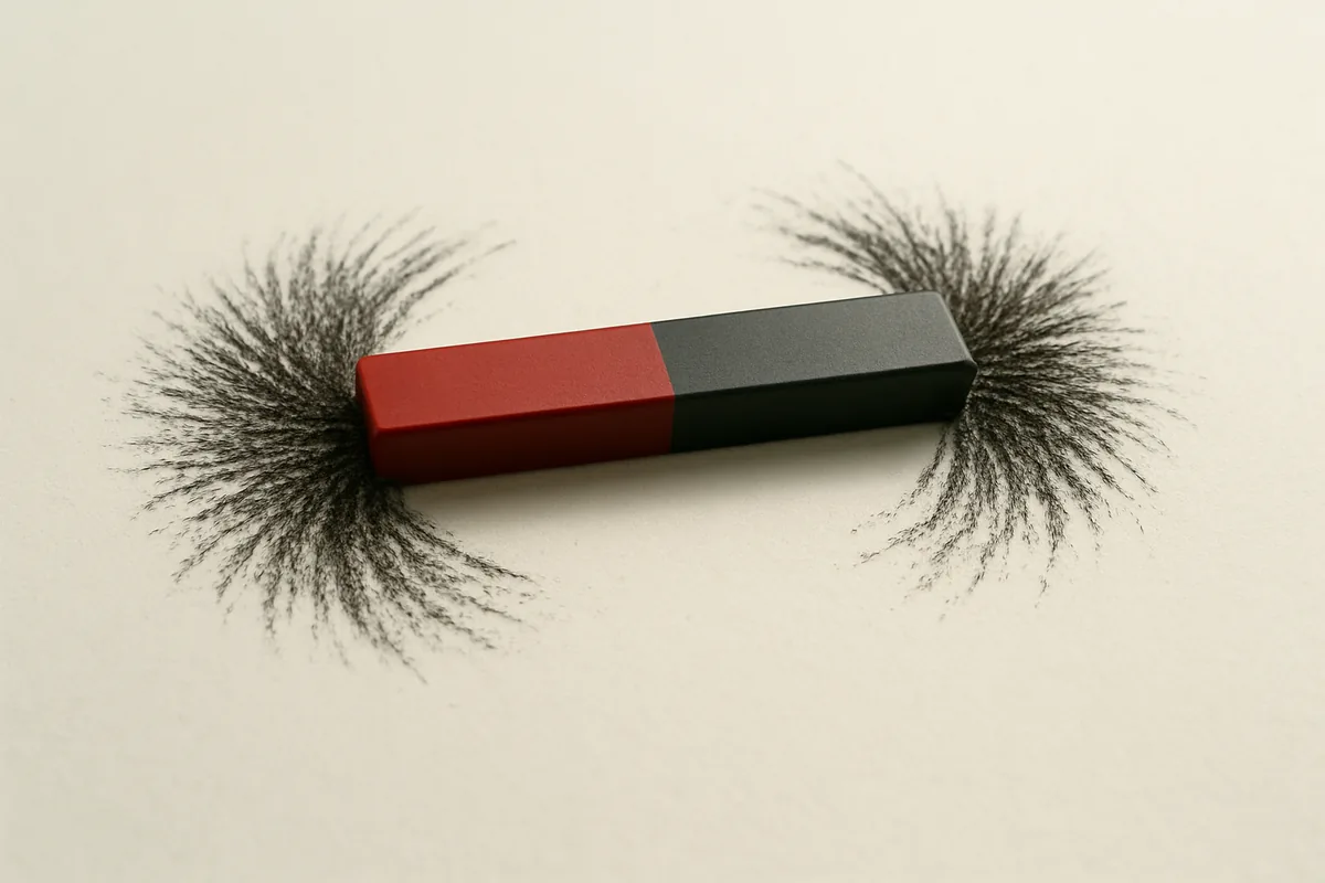
A bar magnet is a simple, elongated magnet, often rectangular in cross-section. Its familiar shape makes it useful for observing how the poles and surrounding field relate to the magnet’s orientation. A compass or iron filings can reveal different aspects of the field around it. The bar magnet page describes its form and field behavior in more detail.
Bar Magnet Form and Poles
A bar magnet is typically a solid, elongated block or rod with a length much greater than its width and thickness. In a common classroom model, one pole is near each short end: the ends are marked north and south, while the broad faces connect them along the length. The poles are not separate pieces; they belong to the same magnet. The magnetic field extends through the space around the bar and loops from one end toward the other outside the magnet. Its pattern is strongest near the ends, where a compass responds more noticeably than it does farther away. The field’s direction at a point depends on where that point is relative to the magnet, so moving a compass around the bar changes the direction in which its needle aligns. Turning the bar changes the field’s orientation in the room without changing which end is north or south. For example, rotating it a quarter turn on a tabletop shifts the field pattern with it. The bar magnet page gives a closer look at this shape and the field around it.
Demonstrations and Uses
A small compass provides a clear demonstration: move it around a bar magnet and note how the needle turns at different positions. Iron filings sprinkled on a sheet above the magnet form curved lines that make the field pattern visible; the filings show the pattern, while the compass indicates its local direction. For a practical example, bring the bar near a steel paper clip or an iron nail and observe whether it is attracted. These objects contain ferromagnetic material, unlike aluminum or wood, which are not attracted in the same way. Bar magnets also serve in classroom experiments and basic magnetic demonstrations because their straight form makes orientation easy to track. For shape details and field behavior, see the bar magnet page. Choose a bar magnet when a simple, visible demonstration is the main goal.
Magnet Shapes
A magnet’s outline affects how it sits in a device, how it can be secured, and which faces are accessible. Disc, cylinder, ring, and block forms each suit different assembly layouts. The orientation of the magnetized poles also matters: a disc can be magnetized through its flat faces, while a ring may be designed for axial or diametric magnetization. The comparison below focuses on fit and mounting rather than ranking shapes by strength.
Common Magnet Shapes
Disc, cylinder, ring, and block magnets differ in their footprint and mounting options. The dimensions below are illustrative examples, not fixed industry sizes; manufacturers offer many other proportions and magnetization directions.
| Shape | Geometry and example dimensions | Mounting options | Useful orientation and fit |
|---|---|---|---|
| Disc | A short circular body; for example, 10 mm diameter by 2 mm thick. | Fits a round, shallow pocket or a flat surface secured with adhesive. A close-fitting recess can keep the disc centered. | Often magnetized axially, with north and south poles on the two flat faces. This suits face-to-face contact or a shallow circular seat. |
| Cylinder | A round body longer than a disc; for example, 10 mm diameter by 20 mm long. | Can slide into a drilled cylindrical bore or tube. A snug bore supports the sides while leaving one or both ends accessible. | Axial magnetization places the poles on the end faces; diametric magnetization places them on opposite sides of the curved surface. Check the specified orientation before assembly. |
| Ring | A circular body with one central through-hole; for example, 10 mm outside diameter and 4 mm inside diameter. | The hole can accommodate a screw or locating pin when its dimensions and the fixing method are compatible. A ring can also fit around a shaft. | Axial magnetization places poles on the flat annular faces; diametric magnetization places them across opposite sides. The bore helps align the magnet around a central component. |
| Block | A rectangular prism with six faces; for example, 20 × 10 × 5 mm. | Flat faces are convenient for adhesive bonding, a retaining plate, or a fitted rectangular pocket. The straight edges can simplify alignment in a housing. | Magnetization may run through the thickness, width, or length, depending on the design. Confirm which pair of faces carries the poles to match the assembly. |
A magnet’s outline does not establish its strength. Material, grade, volume, magnetization direction, and the distance to the target all affect performance, so compare product specifications as well as dimensions. For assembly fit, first identify the available cavity and the faces that must remain exposed.
Choosing a Shape for Fit
Start with the space available: a shallow circular recess may suit a disc, a deep bore a cylinder, a shaft a ring, and a flat rectangular seat a block. Check the contact area against the mating surface; a flat block face or disc face may provide a more direct seat than a curved side. Then choose a mounting method that fits the assembly, such as a ring around a pin or a block held in a pocket. Finally, match the pole orientation to the required magnetic field direction. The best shape is the one that fits securely and presents the correct working face.

Choosing a Magnet
Choose a magnet by matching its design to the job, the environment, and the way it will be mounted. A compact magnet may suit a sensor but not a fixture that must hold a load across a gap. Material, grade, dimensions, and operating conditions all affect the result. Compare force ratings only when their test conditions are relevant to your installation.
Selection Factors
Start by defining the task: locating a part, holding a cover, actuating a sensor, or supporting a fixture. The required holding direction and duty cycle help narrow the options.
Check these practical criteria before choosing a product:
- Application: A cabinet catch needs reliable holding during routine opening, while a sensor target may need only enough attraction to stay in a set position.
- Material: Ferrite suits many humid, lower-cost uses; neodymium provides stronger attraction in compact assemblies but generally needs a protective coating against corrosion.
- Shape: A disc fits a round recess, a block can provide a broad mounting face, and a ring accommodates a central screw or shaft.
- Grade: Compare grades within the same magnet material; for neodymium, N35 and N52 indicate different maximum energy products, not guaranteed installed holding forces.
- Dimensions: Diameter, thickness, and pole-face area affect the available force and fit; check the complete part dimensions against the recess and surrounding hardware.
- Temperature and corrosion: Standard neodymium grades are often rated near 80°C, while some high-temperature grades tolerate more; confirm the exact grade and coating limits.
- Holding conditions: Account for any air gap, the flatness and thickness of the contact surface, and whether the load pulls directly away or slides sideways.
Confirm dimensions and environmental limits from the supplier’s data for the exact part, since coatings and grades vary. A good match is the smallest suitable magnet that fits the mounting and operating conditions.
Pull Force and Real Conditions
A published pull-force rating is a result from a defined test, not a promise of the same holding force in every installation. Manufacturers commonly measure direct separation from a thick, flat steel plate, with clean, close contact and controlled test conditions. The rating is most useful for comparing products tested in the same way.
Installed performance can be lower when a coating, paint, dirt, or uneven surface creates a gap; even a thin gap reduces attraction. Thin steel may not provide the same magnetic path as a thick plate, and rough or curved contact can reduce the effective area. A sideways load acts in shear rather than direct pull, while vibration, impacts, or repeated movement introduce dynamic forces that a static rating does not capture. For a reliable fit, test the magnet on the actual contact material and in the intended load direction.
Magnet Fishing
Magnet fishing uses a strong fishing magnet attached to a rope to retrieve ferromagnetic objects from rivers, canals, ponds, and other waters. Finds can range from small iron fragments to larger steel items, depending on what lies on the bottom and whether the magnet can grip it. A successful outing depends on matching the retrieval method to the location and the object, rather than simply casting as far as possible. Before setting out, check access rules, prepare suitable equipment, and plan how recovered debris will be handled.
How Magnet Fishing Works
A fishing magnet is fastened to a rope and lowered or cast into water to search for objects made mainly from iron or steel. These ferromagnetic materials are attracted to the magnet, which can attach to an exposed surface or edge when the two make contact. Aluminum, copper, brass, and many stainless-steel alloys will not be reliably retrieved this way, so a metal object is not automatically a suitable find.
Once the magnet catches an object, tension on the rope transfers the pull to the find. The person retrieving it draws the line in steadily, keeping the magnet engaged as the object moves across the bed and toward the bank or boat. A broad, flat item may be easier to hold than a narrow piece with little contact area; mud, weeds, rust, and the object’s weight can also affect whether it stays attached.
Retrieval is therefore a process of contact, attachment, and controlled movement through the water. If an object slips free, the magnet can be lowered or cast again to search nearby, since the item may have shifted only a short distance. The rope also provides a way to bring the magnet back when it has not caught anything, making each pass a search rather than a guaranteed recovery.
Preparation and Responsible Recovery
Use this checklist to plan a session from access to cleanup, with the location and likely finds in mind.
- Confirm that you have permission to access the bank or launch point, and check local rules for magnet fishing, water access, and removing objects.
- Choose a fishing magnet and rope suited to the outing; inspect the attachment, knots, and line for damage, and bring gloves and a container.
- Select a stable, accessible spot away from boat traffic, steep edges, and fast-moving water; check weather and avoid casting near other people.
- Cast or lower the magnet into a clear search area, keep the rope controlled, and retrieve it steadily rather than wrapping the line around your hand.
- Assess each find before lifting it: heavy, sharp, or unidentified objects can injure you, so keep others clear and do not handle suspected hazardous items.
- Separate recoverable objects from rubbish, take ordinary debris away for appropriate disposal, and follow local directions for bulky or potentially hazardous finds.
For a first outing, a permitted, accessible bank and a short, controlled search make it easier to manage both the equipment and the finds. Leave the site clean and stop if conditions or an object become unsafe.
Magnet Fishing Kits
Magnet fishing kits pair a magnet with equipment for attaching, lowering, and retrieving it. A bundle may contain only the core components or add items such as gloves and a grappling hook. Contents and specifications vary by seller, so the word “kit” does not guarantee a standard setup. Compare each component with the intended location and the way you plan to handle the equipment.
Kit Configurations
Some configurations center on a single-sided magnet, designed to concentrate its magnetic face toward the object below it. Others use a double-sided design, with magnetic faces on opposite sides; the choice affects how the magnet can contact metal as it moves. Kits may also differ in the magnet’s shape, size, and attachment point, so check the product description rather than assuming that two similarly named bundles have the same design.
The connection can be a threaded eye bolt or another attachment arrangement, while the supplied rope varies in length, thickness, and construction. These details matter together: the rope must suit the attachment point and the conditions where it will be used. Some bundles include gloves, a carabiner, a grappling hook, or thread-locking compound; others leave these items to the buyer. Even basic components such as rope and gloves are not guaranteed to be included, and their specifications are not standardized across kits.
Read the inventory and component specifications before comparing bundle prices. A kit with extra gear may be convenient, but only if those items match the magnet and the intended task.
Comparing Kit Criteria
Start with the intended use: a compact setup for occasional recovery from a shallow, accessible spot has different requirements from equipment meant for repeated use or a deeper location. Compare the magnet design with the likely approach to the target, then check that the rope’s length and construction suit the distance and expected handling. A longer rope is not automatically a better fit if it is difficult to manage at the site.
Inspect how the rope connects to the magnet, including the attachment type and whether the connection can be secured against loosening. Check what is actually supplied for handling, such as gloves, and whether any additional gear is needed for the planned setup. Product descriptions can help establish these details, but a bundle label alone does not establish performance or compatibility. The practical choice is the simplest kit whose magnet, rope, attachment, and included gear all suit the location and task.
Magnet Terms
Magnet specifications use several terms that describe different properties. A field reading describes magnetic conditions at a location, while a pull-force rating reports a force under a particular test setup. Gauss is a unit for magnetic flux density; an NdFeB N-grade describes a material property instead. Knowing what each value represents makes product specifications easier to compare.
Field, Poles, and Pull Force
These glossary definitions distinguish the magnetic conditions around a magnet from a force measured in a test.
- Magnetic field: a vector description of magnetic influence at each point; its direction and magnitude vary with position, and flux density B is commonly reported in tesla or gauss.
- Magnet poles: the two regions conventionally called north and south, where a magnet’s external field is strongest and its field pattern is concentrated.
- Pull force: the force needed to detach a magnet from a specified ferromagnetic target, usually stated in newtons or pounds-force.
- Flux density B: a measure of magnetic flux per unit area; a reading applies at a stated location, such as a magnet’s surface, rather than describing total holding force.
- Test condition: the target’s material and thickness, contact surface, air gap, and direction of loading affect the pull-force result reported for a magnet.
A field reading and a pull-force figure are not interchangeable: gauss or tesla describes flux density, whereas newtons or pounds-force describes a mechanical test result. Compare pull ratings only when the test setup is also known.
Gauss and N-Grade
Gauss (G) is a unit of magnetic flux density, the quantity commonly represented by B. One gauss equals 0.0001 tesla, and 10,000 gauss equal 1 tesla. A gauss reading therefore describes flux density at a measurement point; it is not a force unit and cannot by itself state how much weight a magnet will hold.
An NdFeB N-grade, such as N35, indicates the magnet material’s maximum energy product, often written as BHmax and expressed in megagauss-oersteds (MGOe). The grade reflects the material’s potential magnetic performance, not a direct pull-force rating. Two magnets with the same N-grade can produce different pull forces because their dimensions and test conditions differ. For practical comparisons, check the stated pull force and test setup separately from the gauss reading and N-grade.
Using This Guide
Magnet Guide is an independent English-language information guide, not a shop, service provider, school, or organization. It offers information rather than products or services. Its guides move from core concepts to materials, shapes, and applications. Start with the fundamentals if you are new to magnet terminology, then follow the topics that match your question.
A Route Through the Guides
Magnet Basics introduces the vocabulary used throughout the guides. The permanent and temporary magnetism pages compare magnet categories before you choose a specific material. This sequence provides a foundation for later discussions of magnet materials and their uses.
Next, use the neodymium guide for information about that material and its forms, the bar-magnet guide for a familiar format, and the magnet-shapes guide when dimensions or available space matter. Readers comparing types of magnets can move among these pages without treating material and shape as the same choice. The magnet terminology guide is a useful companion when a specification includes terms such as N-grade, gauss, or pull force.
The choosing a magnet guide helps you consider factors involved in matching a magnet to an application. For outdoor recovery, the magnet-fishing guide is a useful next step, followed by the kit guide for comparing common configurations. The magnet uses information connects these topics with industrial and everyday applications. A practical route is to review the basics, narrow your options by material and shape, then read the guidance for your intended use.
A Route Through the Guides
Start with the fundamentals if you are new to magnet terminology, then follow the topics that match your question.